
Tallerea signal box - Aregntinia

Pictured above is the three story cabin, it appears that the operating floor is accesible via the footbridge.

Close up of the left hand end of the lever frame, with the 3 block instruments in grey boxed situated on top of the shelf.
Although all the signals are electomechinical in operation, all the signal indications strainght forward red or green indicators.

This is a closeup of the center of the lever frame and closeup of the 3 block instruments

Closeup of the manufactures lable which reads, 'Westinghouse Brake & Saxby Signal Co. Ltd., Style B, Serial Nº 152, London & Chippenham.'The leveres 21 through to 27 are points, with 28,29 & 30 are signals, anormal indication of the points on lever 32 is clearly seen.

Closeup of Lever 9 onwards

Left hand end of the track diagram

Center section of the track diagram

right hand section of the diagram

Closeup detail photograph of the signal cabina clearly showing point and signal lever numbers along with the track circuit numbers.
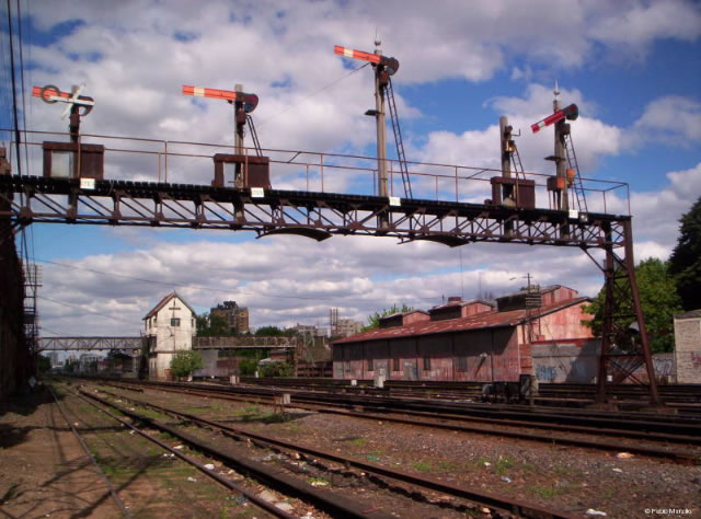
Left to right, Signals 3,5 [Down auxillary home] ,9 [Down main home] & 7. Notice that signal 3 on the left which is a shunt signal is now out of use as there is a white cross on it.
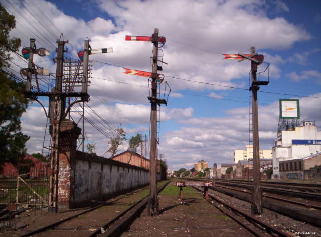
The isolated distant signal is farther from the box, and it is Nº 8, applies to the main line which leads to down home signal Nº9 on the gantry.
Then we have the double arm signal: the stop arm is Nº16 of the adjacent Cabin Liniers, it´s seems to be an advance starting; the distant arm is Nº4 of Cabin Talleres and applies to auxiliary line which leads towards down home signal Nº5, with 3 possible routes: 4, D and G.
The fact is that a great part of the auxiliary track was removed, that is the reason of the buffer stop, and obviously the intention of the signal no longer has sense, and finally the isolated distant signal Nº 8 doesn´t work.
