
Surbiton NX Panel signal box
Introduction
Surbiton NX Panel signal box was located just south of Surbiton Station on the Waterloo to Woking main line in Surrey. The panel was built by Westinghouse Brake and Signal Co. Ltd and was commissioned in two stages 1st March 1970 which was Surbiton To Walton on Thames and 22nd March 1970 which was Walton on Thames to Byfleet and New Haw and the Chertsey branch. The Panel is constructed with 40mm x 40mm tiles and was a Westinghouse M1 style panel It continued in use until its operation was take over the Woking Signalling center scheme on 15th April 1988. The box was always double manned by two signalmen.
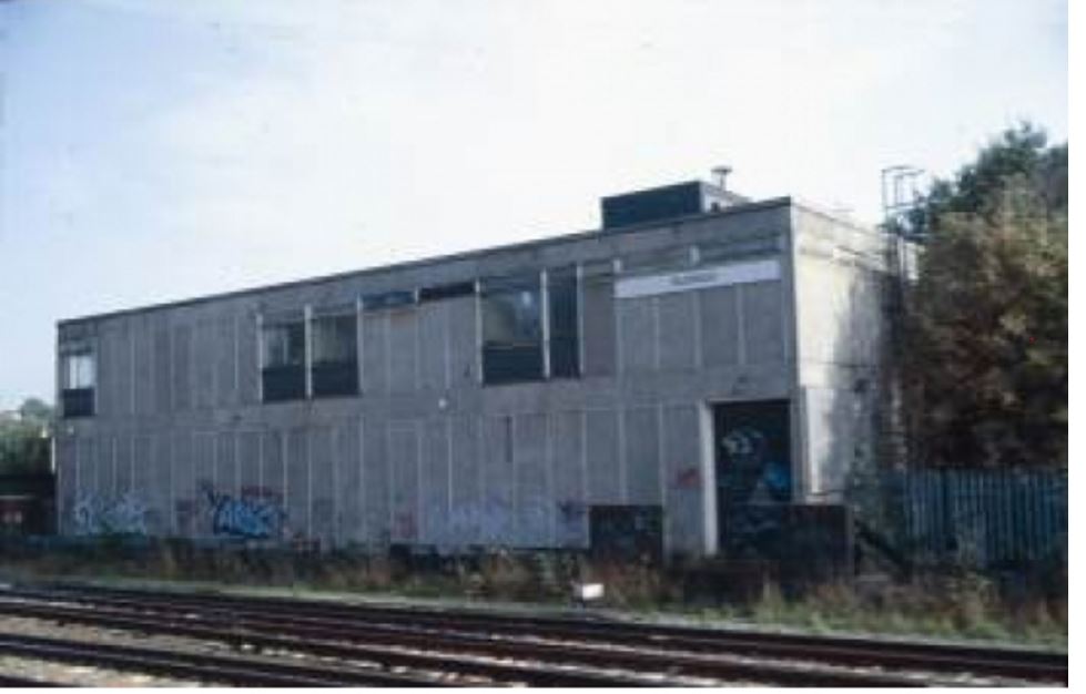
Above: Surbiton NX Panel signal box exterior view, (British Railways, Southern Region) signal box, photographed 12/1/01. From a colour transparency by Phil Deans.
The Panel was a NX Push-Push (NX(PP) Generally one button at the signal: acts as entrance button for route in advance and exit button for route in rear. Each tile containing just one route light / track circuit aperture each and with push-buttons having a shallow, rounded-edged escutcheon
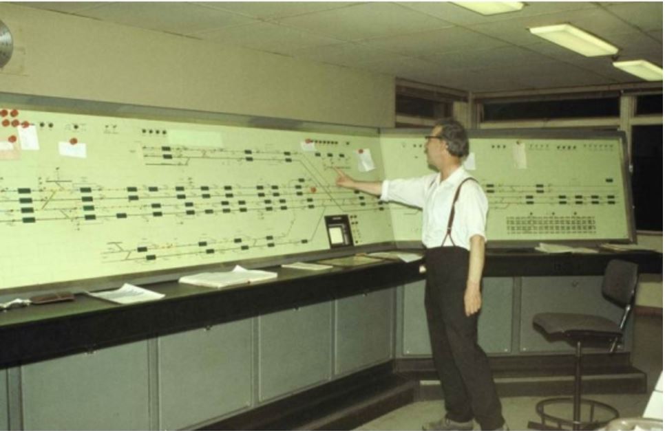
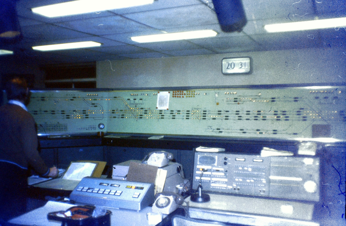
Above: Interior of Surbiton NX Panel Surbiton end, (British Railways, Southern Region) signal box, photographed 19/7/78. From a colour transparency by N L Cadge.
Signalman has been identified as Johny Rowbotham
When the signal box was opened in 1970 there were 3 gate boxes with mechanical level crossing gates, Addlestone, Hampton Court and Cooks Crossing adjacent to Oxshott station. Addlestone gate box closed 6 January 1974 followed by Cooks crossing gate box on 28 April 1974. (Coxes Lock Mill Crossing (aka Coxes Mill Crossing), was never a block post. When in operation it had 3 levers until its abolition on 18th January 1970, after which the crossing reverted to occupation crossing status as part of Surbiton resignalling works.)
The level crossing were converted to and Remotely Controlled Full level crossing barriers with black and white CCTV were used to supervise the level crossings. The level crossing controls were separate from the main signal remote control systems and used the Frequency Division Multiplex (FDM) system. CCTV signals were passed over conventional coax cable with amplifiers as necessary to the monitors at Surbiton.
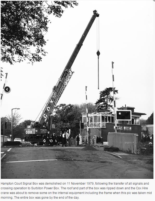
It took until November 1979 for Hampton Court gate box to be converted to Remotely Controlled Full level crossing barriers with CCTV. The old gate box was demolished on 11 November 1979
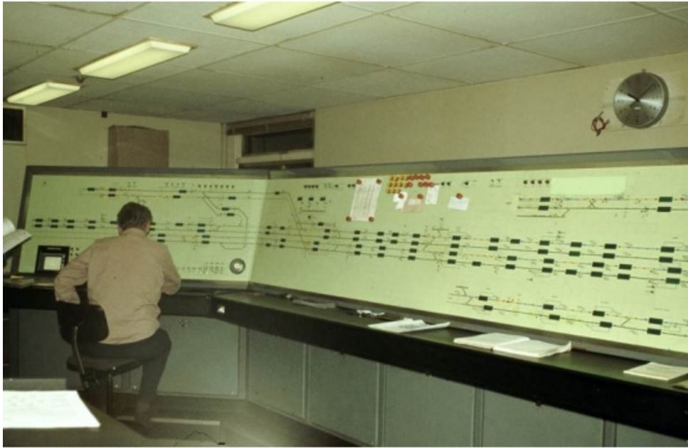
Interior of Surbiton_NX_Panel_Weybridge_end (British Railways, Southern Region) signal box, photographed 19/7/78. From a colour transparency by N L Cadge.
With respect to the signals, the main line was predominantly 4 aspect, with 2 or 3 aspect on the branch lines. However on the 4 track main lines, there was insufficient braking distance for 90 mile per hour running between Woking and New Malden without special signal aspect controls. The special arrangements were the use of the 'double' double yellow signal aspect which increase the necessary braking distance to safely stop a train.
Therefore the signals showed, Green, Double Yellow, Double Yellow, Yellow then Red aspects respectively. (G, YY, YY, Y, R). All signals are fitted with Green extra strength AWS track equipment throughout the area. There was one searchlight 3 aspect signal at Addlestone station platform just before the level crossing. All signals that worked automatically were prefixed with a WAxxx name plate, where as all control signals had a 'S' prefix name plate All points were fitted with Westinghouse M63 style point machines battery driven at 130vDC using central battery in the relay rooms.
All Relays rooms were "free wired" using Westinghouse Q style relays, the relay room interlockings consists of separate relays performing the vital functions which are interconnected in a design which is specific to that location. The non-vital functions were also performed by Westinghouse plug in Post Office style relays using either directly fed or electronic fed systems.
Booking Desk / Train Announcement Desk
The Booking Desk and Train Announcement Desk was used to record iccendents and irregularities, and more importantly in about late 1973 / 74 a station annoucement system was installed to most stations on the line, so pre-recorded and other messages could be sent to the station public address system along the line.
Remote Override Control (ROC)
Override controls are often provided in connection with remote interlockings controlled by Time Division Multiplex (TDM) or Frequency Division Multiplex (FDM) links. They allow a small number of priority routes to be set and signals to work automatically if normal control from the interface is lost. These are normally just one of the controls positioned on the interface amongst the others provided for normal signalling. However, in the case of Surbitons various relay interlockings a separate interface is sometimes provided for the control of override systems.
Signalmen
We have been able to identify the following people as signalmen when operated the signal box
Johny Rowbotham, Phil Davies, Alan Hoade.
We have also been able to identify the following people in the Signal and Telegraph department located at the Panel Mark Adlington
(there were 8 technicians in total, they worked in pairs, plus one senior technicians on day shift. 4 technicians were on day shift, 2 on late turn and 2 on nights, Cover was 24/7.
Cine Film Footage
Video is from the authors own cine film taken in 1972-1974 whilst he was an Signal and Telecommunications Technician at Surbiton signal box.
Relay Rooms
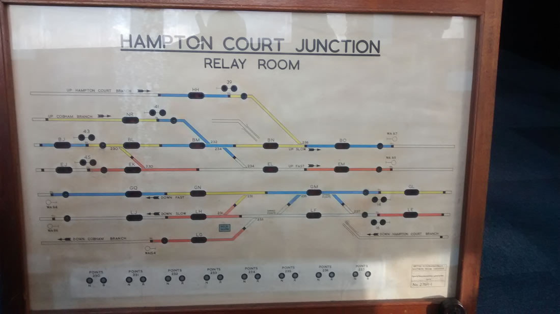
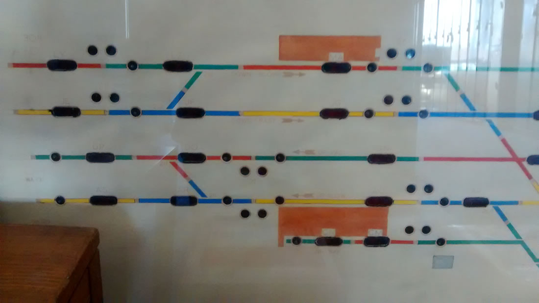
There were 4 remote Relay Rooms (interlocking) at Hampton Court Junction, Hampton Court, Walton on Thames and Weybridge respectively.
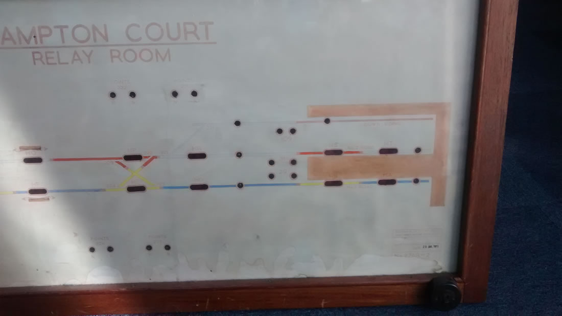
Above:In the view above the Up Sidings which were operated by a the gate box lever frame have been removed,the power points by platform 1 has also been removed
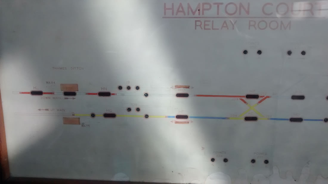
Hampton Court and Hampton Court Junction were direct fed using direct fed micro core cabling for control and indication.
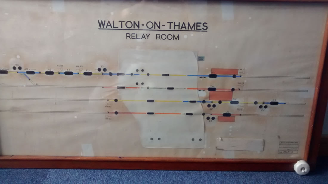
Above:In the view above the Up Main to Up Local and the Down Local to Down Main points have been removed, along with the Up Sidings which were operated by a mechanical ground frame immediately outside the relay room.
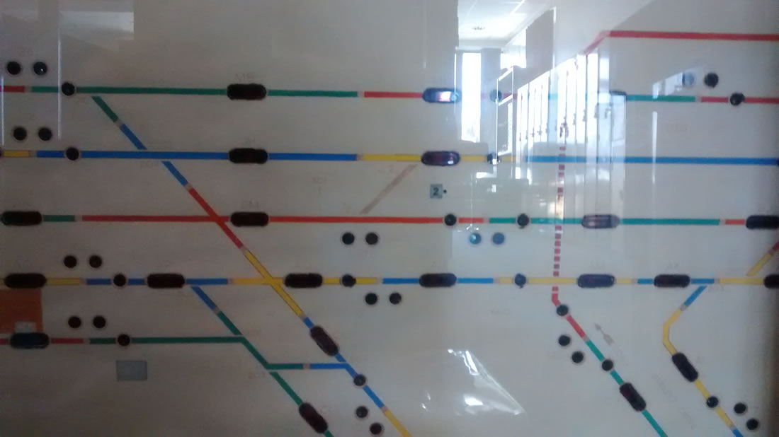
Weybridge was connected with a Westinghouse Time Division Multiplex (TMD) control and indication system. Walton on Thames as also connected to Weybridge TDM system via a local microcore cable from Walton on Thames to Weybridge relay room.
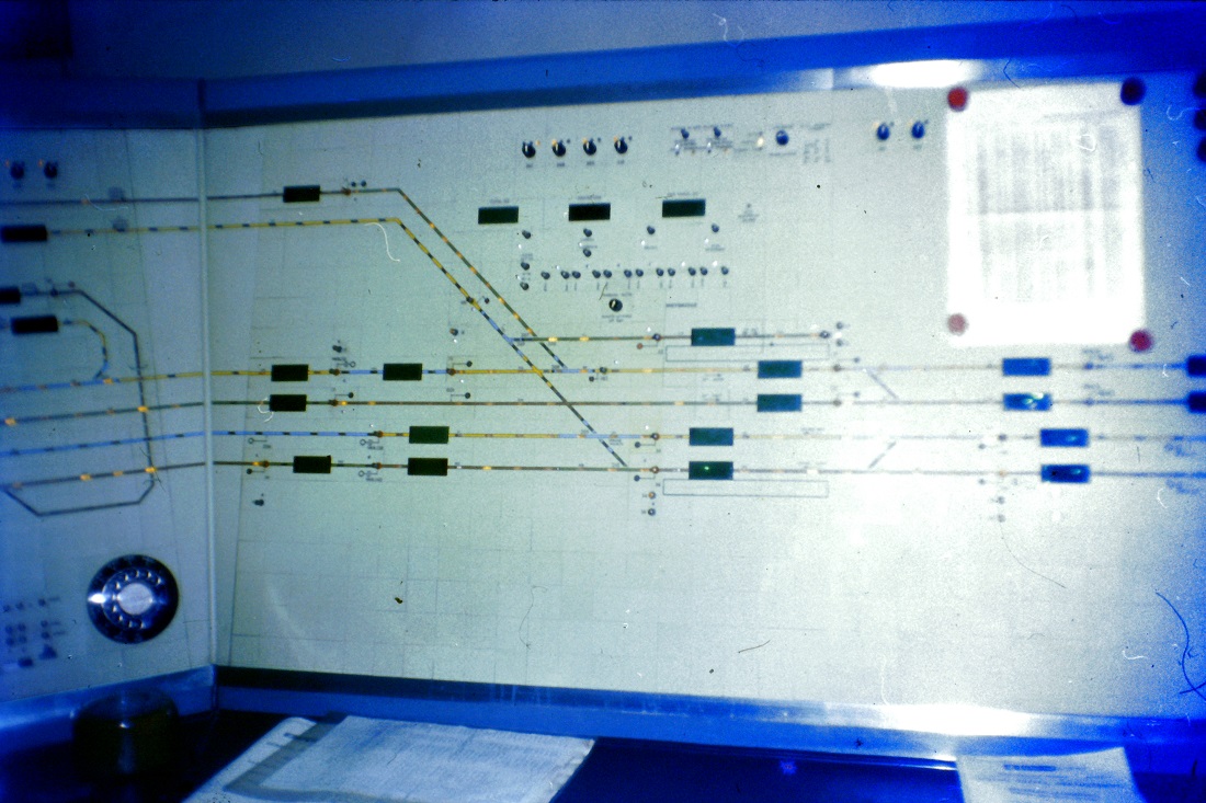
Local Control Panels
The remote relay rooms had Local Control Panel (LCP) for emergency use. it was initiated with a Key switch. They were intended for temporary operation as part of stage works or as LCPs, with the controls consisting of three position GPO Type 1000 telephone-concentrator-style key switches for points and signals. Those for signals are sprung to return to the middle position, being pressed down to simulate the pressing in of a conventional NX(PP) button, and being pressed up to simulate the pulling up of a button. Points switches are pressed to the Normal or Reverse position to call the points, where they remain until reset, being normally in the centre position for route-setting. The route-setting process is as for NX(PP) but with the switches taking the place of conventional NX buttons. Each Relay Room Local Control Panel had a conventional southern railway style track diagram with track lights, and signal and point indicators on the drawing.
Addlestone Gate Box
This signal box was located right next to Addlestone station, and originally controlled the mechanical level crossing gates. This picture was probably taken immediately after the full level crossing barriers were installed, but before control passed to Surbiton Panel. The signal box also control access to the Up Siding via a trailing connection immediately to the left of the box.

The white fencing just outside the signal box and the mechanical cranks, mechanical level crossing gates and rods for the mechanical gates are missing, I am guessing picture was taken around autumn 1973 as the box windows are open, and the engineers are in shirt and no jumpers or coats
Addlestone gate box closed 6 January 1974. Reporoduced by kind permission of Colin J. Marsden of Dawlish Trains (©)
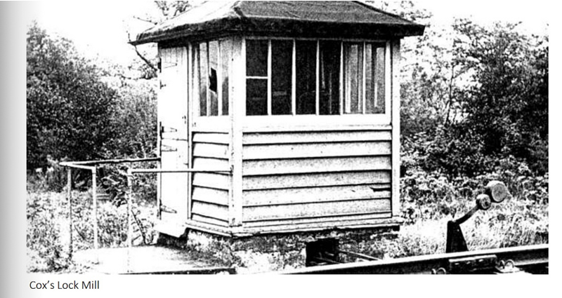
Coxes Lock Mill Crossing
Coxes Lock Mill Crossing (aka Coxes Mill Crossing), was never a block post. When in operation it had 3 levers until its abolition on 18th January 1970, after which the crossing reverted to occupation crossing status as part of Surbiton resignalling works.
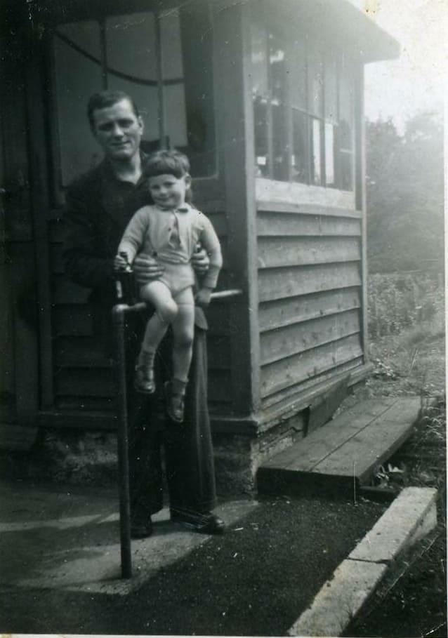
Peter Champion with his children at Coxes Mill Crossing box date unknown
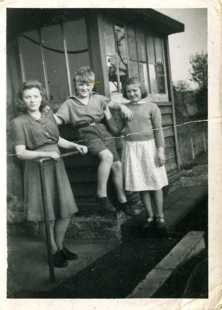
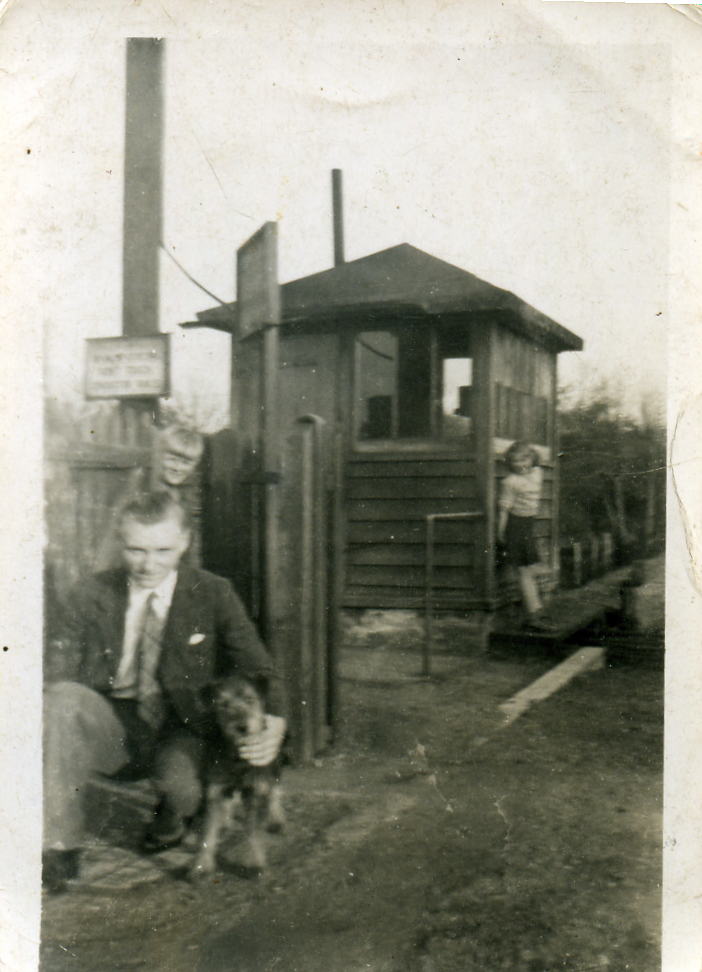
Rita, David and Eileen Champiom at Coxes Lock Mill Level Crossing date unknown
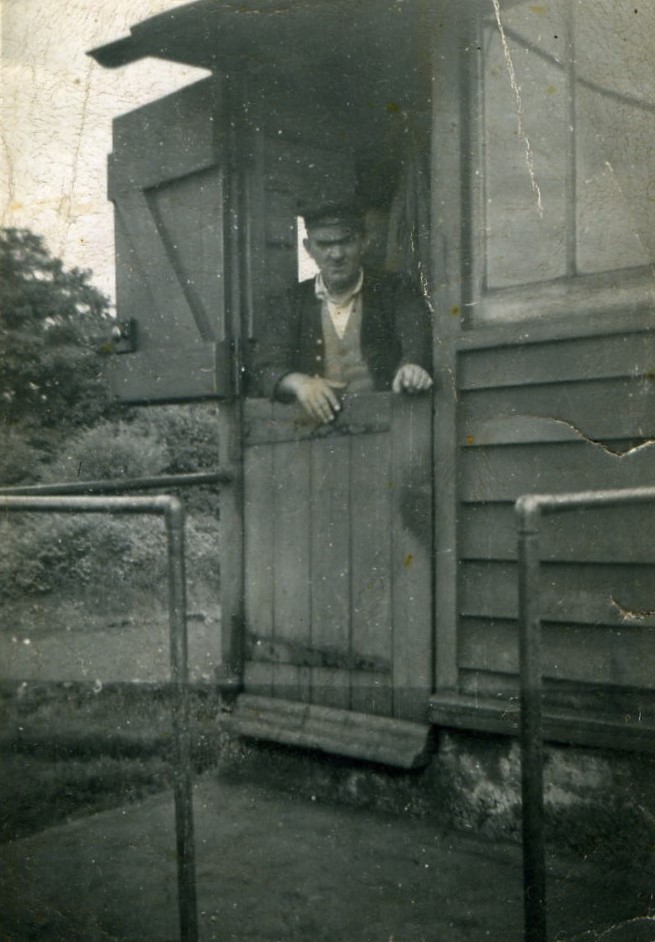
William Champion at Coxes Lock Mill Crossing box = date unknown
Cooks Crossing Gate Box
Cooks crossing is / was located south of Oxshott station. Cook's Crossing (named after John Early Cook, the owner of the brickyards), the railway crossing had three lines: two for the electrified main line to Guildford via Cobham and Stoke D'Abernon and a single track to the brickyards. The brick yard closed in 1958.
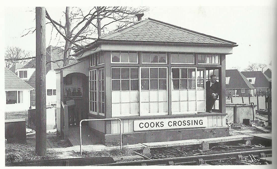
The Crossing box became a block post on 22nd January 1951 when Oxshott station signal box was demolished. It reverted to a gat box again when colour light signals were brought into use when Surbiton Panel signal box opened on 1st March 1970. At this time mechanical level crossing gates were fitted these were driven by the cranks in the foreground of the picture. Full lifting barriers were installed and control from Surbiton under CCTV control from 28th March 1974. Picture copyright © J Scrace, reproduced by kind permission of Middleton Press, From their Branch Lines around Effingham Junction book in published in 1990 ISBN 0906520746.
Hampton Court (station) Gate Box
This signal box came into use on the 3rd March 1957 taking over control of the then station signal box. On the 1st March 1970 became a Gate Box. On the 29 July 1979 the mechanical gates were replaced with Full level crossing barriers control from the gate box. On the 23 September 1979 CCTV remote control was introduced and control passed to the Surbiton Panel signal box.
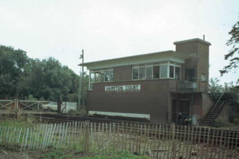
Above: Hampton Court (British Railways, Southern Region) signal box, photographed 19/7/78. From a colour transparency by N L Cadge.
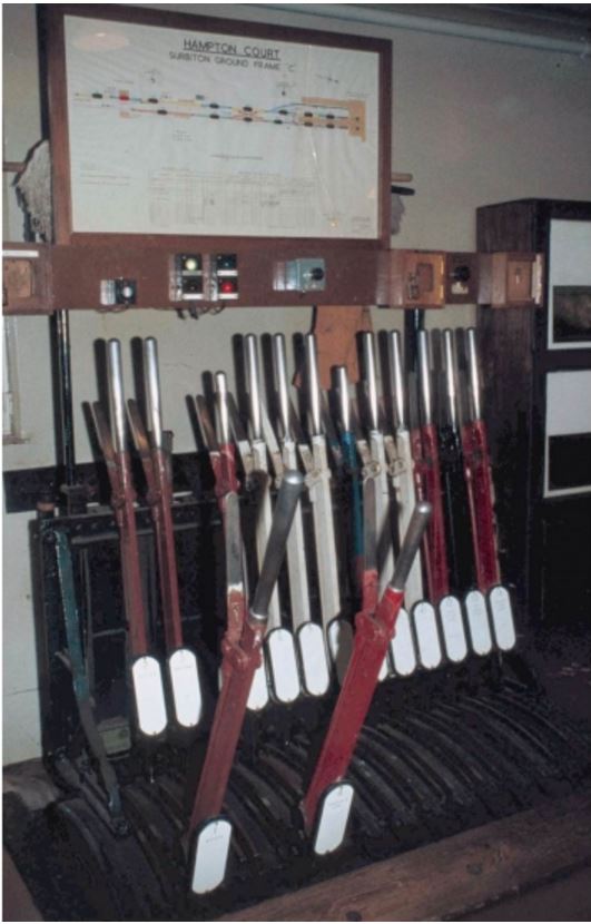
Above: Hampton Court (British Railways, Southern Region) signal box, photographed 19/7/78. From a colour transparency by N L Cadge.
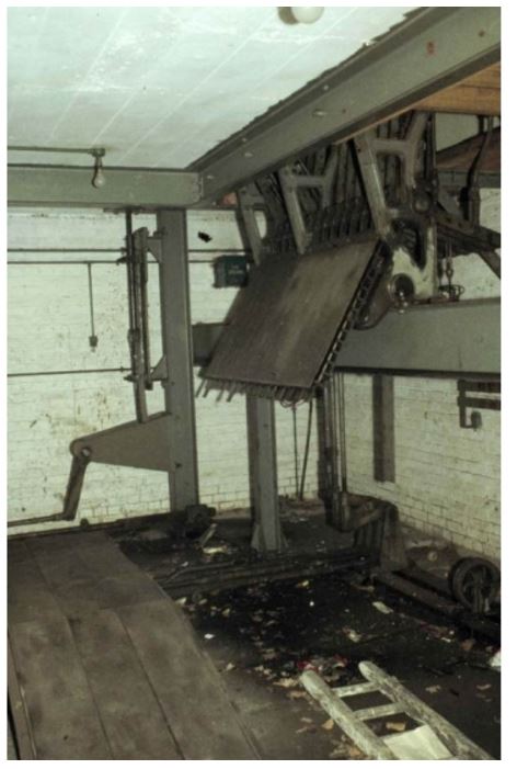
Above: Hampton Court (British Railways, Southern Region) signal box, photographed 19/7/78. From a colour transparency by N L Cadge.
Reporoduced by kind permission of Colin J. Marsden of Dawlish Trains (©)
Southern Region/Signal Repeating AWS (SRAWS)
Originally called "Southern Region AWS", its name was later changed to "Signal Repeating AWS". The SRAWS system repeated the next signal's aspect (and displayed a reminder of the previous signal's aspect) on an indication inside the cab. Any aspect other than green had to be acknowledged by the driver pressing the correct button that corresponded to the indication on display. If the driver did not acknowledge the indication, or the wrong button was pressed, an automatic brake application was initiated. The risk of error from subconscious cancellation was therefore greatly diminished.
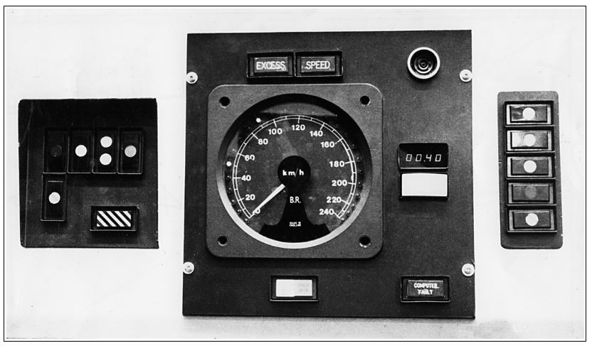
Above: SR AWS Cab setup. Development of SR-AWS, with signal past indications on left and signal approach indications on right. Note the km/h only calibrated speedometer.
During 1971 an experimental form of cab signalling (SRAWS - Signal Repeating AWS) which was being trialled in the up-direction between Byfleet [it may have been Woking] and Raynes Park (as well as in the New Forest area). The cab layout showed the driver the aspect of the next signal and the one that the train had just passed. Its used a coax aerial loop figure of eight in the track with a frequency module in the signal location to pass a radio frequency code to the train depending on the signal aspect. Development of SRAWS ended in 1975 when the British Railways Board dictated that the Southern Region should equip its lines with standard BR AWS.
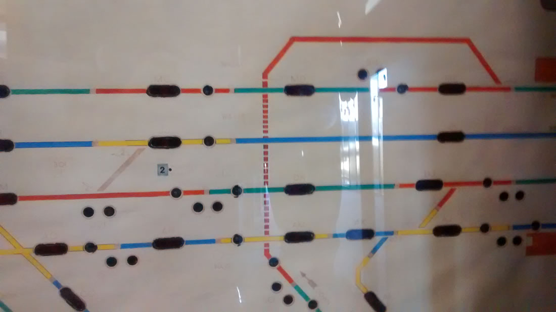
Diagrams
Attached is
![]() INTRODUCTION OF COLOUR LIGHT SIGNALLING BETWEEN COOKS CROSSING, LEATHERHEAD AND EFFINGHAM JUNCTION
INTRODUCTION OF COLOUR LIGHT SIGNALLING BETWEEN COOKS CROSSING, LEATHERHEAD AND EFFINGHAM JUNCTION
![]() INTRODUCTION OF COLOUR LIGHT SIGNALLING AND TRACK CIRCUIT BLOCK WORKING BETWEEN ADDLESTONE AND CHERTSEY
INTRODUCTION OF COLOUR LIGHT SIGNALLING AND TRACK CIRCUIT BLOCK WORKING BETWEEN ADDLESTONE AND CHERTSEY
![]() Bringing into use the new Panel Signal box at Surbiton, Completion of Colour Light signalling within the Area of Surbiton, Cooks crossing, Hampton Court and Walton on Thames.
Bringing into use the new Panel Signal box at Surbiton, Completion of Colour Light signalling within the Area of Surbiton, Cooks crossing, Hampton Court and Walton on Thames.
![]() Extent ion of the area controlled by Surbiton Panel signal box, between Walton on Thames, West Byfleet and Addlestone.
Extent ion of the area controlled by Surbiton Panel signal box, between Walton on Thames, West Byfleet and Addlestone.
These can be downloaded in PDF format,. These diagram(s) are taken from the web site of the Signalling Record Society Research Note37. These images are copyright of the Signalling Record Society, and reproduced by permission.
Adjacent boxes
New Malden to Woking Main Lines
At the London end New Malden signal box was the the adjacent boxes when the panel box box opened, New Malden signal box closed under the Wimbledon signalling centre scheme and the became the Wimbledon signalling centre became the adjacent signalling centre
At the County end Woking Signal box box was the the adjacent boxes when the box opened .
Guildford New Line
Guildford Panel Box was the adjacent signalling centre, Guildford controlled up to Cobham station on the Surbiton scheme
Chertsey Branch
When opened Chertsey signal box was the adjacent box {closed 4th Feb 1934}, this was later transferred to the Feltham signalling centre scheme..
Hampton Court Branch
The Hampton Court branch was controlled from the Surbiton Panel
You can go straight to the signal box listed above, by clicking on the signal box name, provided the signal box name is highlighted.