
Loughton signal box
Loughton signal box was built by London Transport and the frame was installed in 1939-40 but the re-signalling scheme postponed for duration of the Second World War. It was built to the London Transport Type design and opened in 1948 fitted with a 59 lever Westinghouse 'N' frame (frame number 197).
A panel was installed on 29th July 1996, a second panel was installed on 29th July 1996. The frame was replaced by a panel on 26th August 1997.
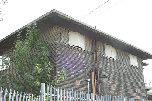
The exterior of the signalbox after it was closed, taken during a station open day 19 Sep 2004.
Picture reproduced by kind permission of © Martin Belam
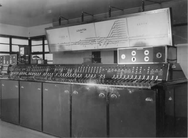
Interior of signal cabin at Loughton.Photographed by Walter A Curtin, Jan 1949

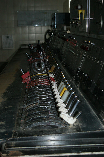
Closup of the telephone concentrator and the first few signal levers in the 59 lever frame
Picture reproduced by kind permission of © Martin Belam
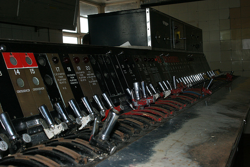
Middle of the lever frame Picture reproduced by kind permission of © Martin Belam
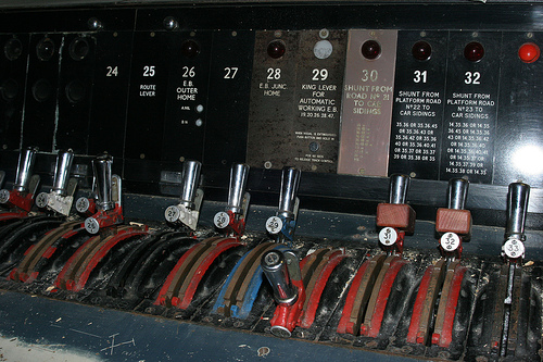
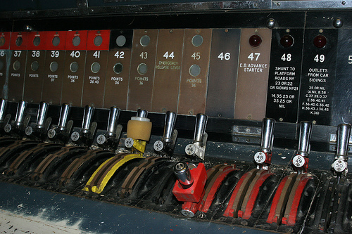
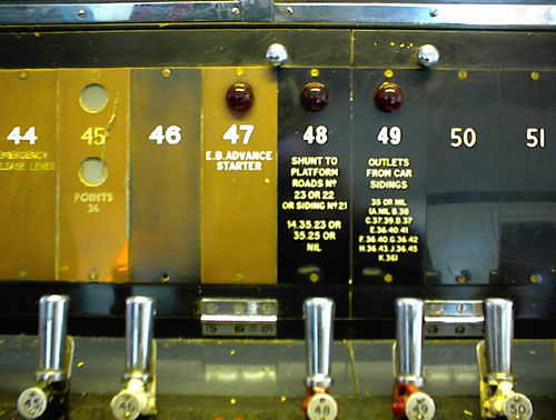
This panel on the lever frame controlled the points in the shed yard . pictures reproduced by kind permission of © Martin Belam
The neat wiring is very clear in the picture which is looking inside the lever frame.
Picture reproduced by kind permission of © Martin Belam
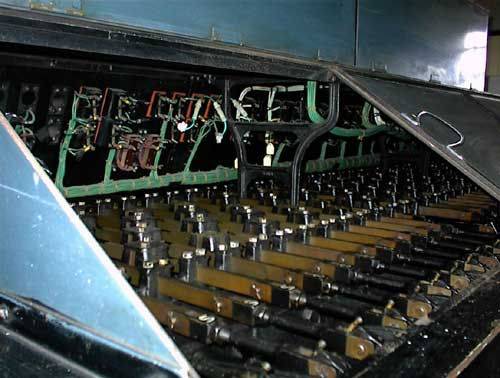
Inside the rear of the lever frame showing the lamp wiring and mechinical / electrical lever locking slides
Picture reproduced by kind permission of © Martin Belam
Diagrams
Attached a railway and signaling track diagram from London Transport Central Line Extention 1946 - 1957. This diagram can be downloaded opened in your browser in Adobe PDF format provided the Adobe browser is loaded, otherwise you will be able to save the file to your computer until such time as you have an Adobe Reader installed to read the file - Adobe reader is available free, just use the Adobe Reader icon below to get your copy. 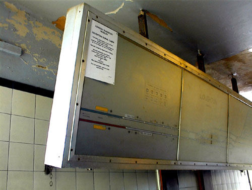
This end of the signals mans track diadram showns THEYDON BOIS station in the yellow shaded block
Picture reproduced by kind permission of © Martin Belam
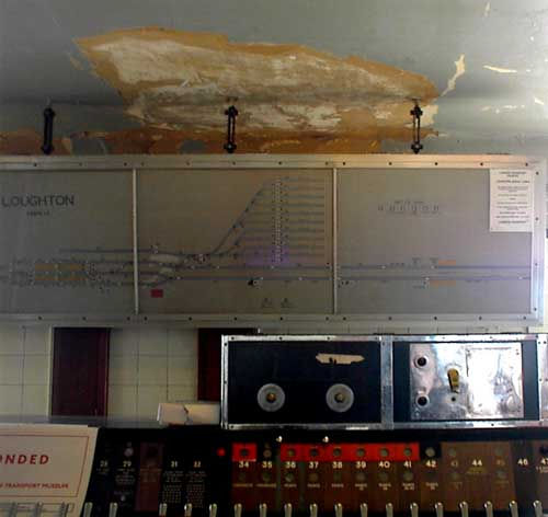
Close up of the centre section of the track diagram, which includes the main Loughton Station platforms as well as the 10 train sidings. Picture reproduced by kind permission of © Martin Belam
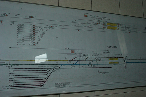
Paper diagram in the relay room showing the station and track layout and signals. The station platforms are the yellow shadded areas on the diagram. Picture reproduced by kind permission of © Martin Belam
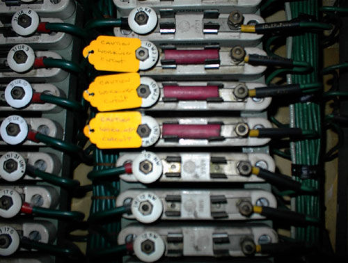
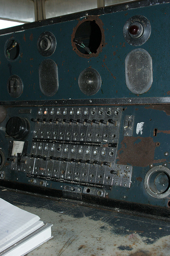
Close up of the Fuse rack and disconnection links Picture reproduced by kind permission of © Martin Belam
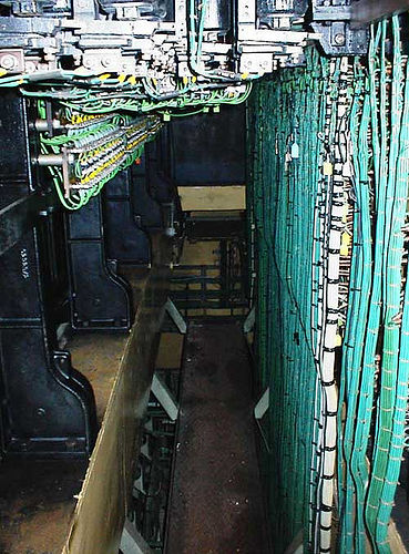
General view of the Fuse and disconnection link frame where the outside cables arrive and are terminated
Picture reproduced by kind permission of © Martin Belam
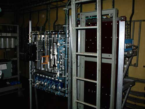
General view of more of the signalling control gear, along with the ladder that allow access to the ceiling area wiring runs. Picture reproduced by kind permission of © Martin Belam
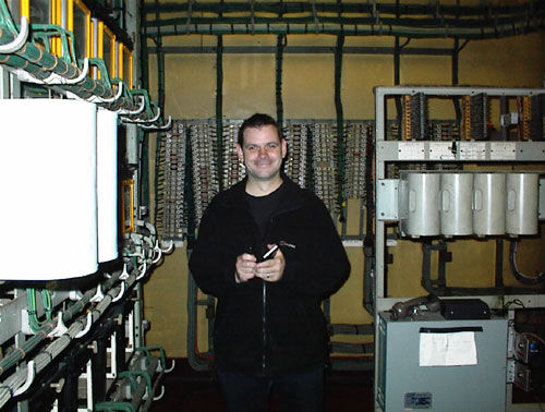
Martin deep in the interior of the signal cabin. Picture reproduced by kind permission of © Martin Belam
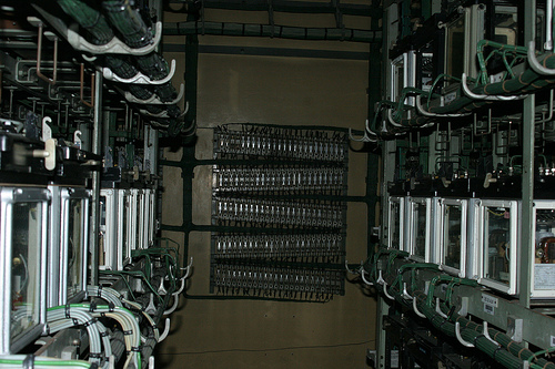
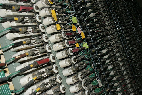
Looking at two relays rack, one set of relays on the left and the other set on the rights, these were used to control the signalling system. Picture reproduced by kind permission of © Martin Belam
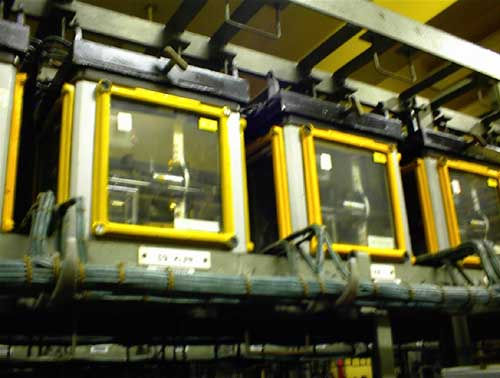
Close up of the Westinghouse Relays, these are all 110 volt AC and are known as 'fish tanks'
Picture reproduced by kind permission of © Martin Belam
Adjacent boxes
Woodford