
Forest Hill signal box
Forest Hill signal box with its Westinghouse Brake & Signal Co. Ltd. Style 'L' Power Lever Frames was opened by British Railways on the 8th October 1950. It was built to the Southern Railway Type 13 ("glasshouse") design and was fitted with a 47 lever Westinghouse 'L' .
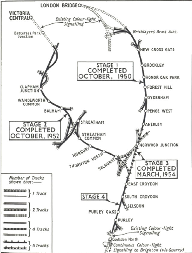
Southern Region Resignalling of the London to Brighton Line which occurred between 1950 to 1955 which aimed to abolish all the semaphore signalling from the south end of the London Bridge scheme and also from just outside of Victoria which met at Windmill Bridge Junction (latterly known as Gloucester Road Junction) north of Croydon, and continued to Coulsdon. The objective was to removing the Sykes Lock and Block working and replacing it with track circuiting and colour light signalling. The whole scheme cost £2 million pounds and involved 11 new signalboxes having a combined total of 841 levers, replacing 32 manual signalboxes with a total of 1,515 full sized levers.
The signalbox only continued in use for 19 years until its operation was take over the Norwood Junction signal box NX Panel on the 15th June 1969. It controlled the Crystal Palace branch junction that diverged just south of Sydenham Station.
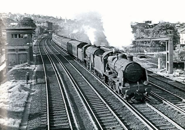
Above: The 'Odeon' style box is seen above with an apparent all round clear view of the surrounding tracks despite the use of illuminated diagrams and magazine type train describers. This photograph was taken on 9th May 1962 with the 5.25pm London Bridge to Reading South train double heading with U class 31796 and Schools class 30916 'Whitgift', the train is unusual in that double heading was seldom used. The siding to the left leads to the goods yard and goods yard head shunt. Picture copyright © J Scrace, reproduced by kind permission of Middleton Press, from their London Bridge to East Croydon book in the Southern Mainlines series published in 1988 ISBN 0906520584
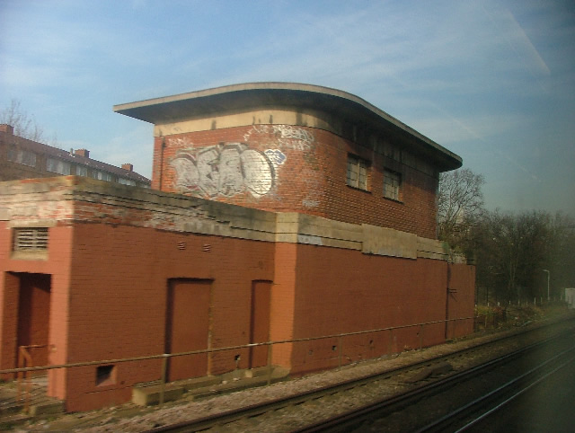
Forest Hill signalbox exterior in 2008 look rather shabby and grafitied but still standing and intact. Picture reproduced by kind permission of Paul Robinson, © Paul Robinson
 The frame is a Westinghouse Style 'L' Power Frame which is all electrically locked. The frame was formed of 11+28+1+7= 47 levers, as the last “lever” space is unavailable. 11 of these levers worked the points, 18 signal levers, 1 special lever was provided with 7 spare levers. when the frame was supplied and installed.
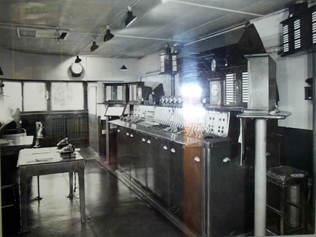
The photograph shows the interior of Forest Hill signal box taken I beleive in the late 1950's or very early 1960's. unfortunatly I have not been able to remove the flash light in the middle of the picture. Picture is courtsey of Nick Wellington.
The Westinghouse Brake & Signal Co. Ltd lever frame, with its indicators behind the levers, the 4 glass roundels showed the signal aspect, being Red, Yellow, Green & 2nd Yellow reading from bottom to top. The train describers sending boxes are fitted on top of the frame box whilst the receiving train describer units are housed between the signalling diagrams. The top indicator behind the signal lever is the "F" light and this became lit when the lever was normal, all points in the route correctly detected and all relevant track circuits clear. You could pull the lever at any time provided that the locking was correct but the signal would not clear unless the "F" light was lit before the lever was pulled. Emergency bell plungers are provided next to adjacent signal boxes, again mounted on the block shelf. Telephone concentrators are provided at each end of the frame at 45 degrees. The desk for train recording is situated in the immediate front area.
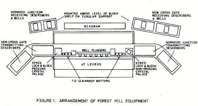
The shelf above the 47 levers was not enough to carry desired equipment, so with the support of tubular steel supports, angled wings were added as extensions to the shelf to carry the transmitting halves for the magazine train describers as shown above in figure 1.
Diagrams
Attached is Southern Region signal instruction 1 notice this and signal instruction 1 track diagram this can be downloaded in PDF format, this covers the opening of Bricklayer Arms Junction to Norwood Junction North signal boxes and their coloured light signalling installation. These diagram(s) are taken from the website of the Signalling Record Society Research Note37. These images are copyright of the Signalling Record Society, and reproduced by permission.Westinghouse brouchure on signal box track diagram coutsey of Andrew K Overton in
Please be aware that these files are large and
can take a while to download depending on your internet providers line speed. typically
file sizes between 300-500K each ![]()
Adjacent boxes
London Bridge (Main & Local Lines ) NorthboundTo the north New Cross Gate, 3m 340yds away, was the adjacent box.
London Bridge (Main & Local Lines ) Southbound
To the south on the Down Local line was Penge West, 1m 541yds away, was the adjacent box.
On the Up Local, Up Main, and Down Main lines, Norwood Junction North was the adjacent box. Norwood Junction North a mechanical box closed on 21/03/1954, and was replaced by Norwood Junction box 2m 1571yds away. Penge West box was closed on 21 August 1966 and then Norwood Junction box was the adjacent box on all four running lines.
Sydenham to Crystal Palace Branch line
Crystal Palace "C" (1m 1017yds from Forest Hill box) was the adjacent box, it was closed on 13/07/1969 when the area was the Crystal Palace area was controlled from a panel installed in Norwood Junction box.