Brighton signal box
Introduction
Brighton signal box with its Westinghouse Brake & Saxby Signal Co. Ltd. Style 'L' Power Lever Frames was erected in 1931/32 when the London to Brighton line was electrified, the signal box opened on the 16th October 1932 to control an intensively used area, Bright station is / was served by a 10 platforms, locomotive sheds, good sheds as well as carriage sheds. Lines converged into the station from 3 directions.
Brighton box closed on 30th March 1985 which is 52 years later, this is when the Three Bridge's Signalling Centre took over all the signalling in the Brighton area. The box was demolished in April 1985.

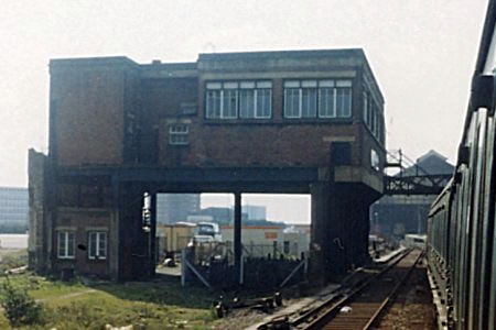
Brighton signal box exterior
is pictured left
in the late 1960's / early 1970's, the building looks odd because this building was originally built into the side of the old Brighton Locomotive Works.
The locomotive works was then demolished leaving the box standing by itself.
pictures reproduced by kind permission of © Graham Floyd.

Brighton signal box exterior
Pictured in 1984 looking rather forlorn and out of use, it was not long after this that the building was demolished.
Picture reproduced by kind permission of © Alan Elliott.

BR(SR) Brighton signal box - c.02/1980. Picture reproduced by kind permission of © John Turner 53A Models of Hull The actual date the image was made is unknown; the indication given is based on the film processing date imprinted on the original slide.

The frame is a Westinghouse Style 'L' Power Frame which is all electrically locked. The frame was formed of 18 x 12 way and 1 x 8 way section which making a total of 225 levers, {18x12}+8}-1 = 225 levers, as the last “lever” space is unavailable. 65 of these levers worked the points, 139 signal levers operated the coloured light signals, with 2 special levers and 19 spare levers were provided when the frame was supplied and installed. This made the working lever total of 206. Picture from SRS archive, This images is copyright of the Signalling Record Society, and reproduced by permission.

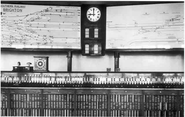
Brighton signal box interior
pictured left is what I think is a publicity picture taken around the1950.
The track diagrams are still the large original versions, and the signalman's uniform is typical of the period.
The 2 track East Coast Line towards Falmer is at the very top.
The London Main Lines are in the centre middle section of the diagram comprising of I think 7 tracks.
The 2 track West Coast Line towards Hove is located at the bottom of the track diagram, these are the Up and Down line towards Portsmouth.
Brighton station is on the far right side of the last track diagram panel.

Brighton signal box interior
The Westinghouse Brake & Signal Co. Ltd lever frame, with its indicators behind the levers.
In 1932 the colours in the 4-aspect outdoor signals, from the bottom up, were still Y, R, YY, G. The present standard sequence of R, Y, G, YY came a little later.
Block bell plungers are provided next to adjacent signal boxes, again mounted on the block shelf. along with Walker's Rotary train describers, these are clearly visible at this end of the lever frame.
Picture reproduced by kind permission of © Alan Elliott.

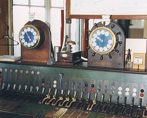
Brighton signal box interior lever frame detail photograph, with two block bells and the ubiquitous train describer between the block bells, adjacent to a modern clock.
Just visible above the signal lenses in the centre of the photograph is the signal lever is the "F" light and this became lit when the lever was normal, all points in the route correctly detected and all relevant track circuits clear.
You could pull the lever at any time provided that the locking was correct but the signal would not clear unless the "F" light was lit before the lever was pulled.
Picture reproduced by kind permission of © Alan Elliott

The Walker's Train Describer consists of a clockwork driven mechanical "Sending" instrument and an electro-mechanical "Receiving" instrument. The left hand Walkers is the recieving instrument, and the right instrument is the sending instrument. Each of these instruments has an identical dial upon which is fixed tablets showing various required destinations and a pointer to indicate the tablet required. The "Sending" instrument has a lever adjacent to each of the tablets, resemble a ship's steering wheel!
Diagrams
Attached is Southern Railway signal instruction 40 notice and signalling instruction 40 track diagram this can be downloaded in PDF format, this covers the opening of Brighton signal box. These diagram(s) are taken from the web site of the Signalling Record Society Research Note37. These images are copyright of the Signalling Record Society, and reproduced by permission.Adjacent boxes
Brighton signal box worked to:-
West Coast line
Hove East (1m 80yds away). Hove East (but re-named Hove "A") box was closed on 16/03/1985 and Three Bridge Signalling Centre became the adjacent box. This lasted until Brighton box closed.
East Coast line
London Road (796yds away). London Road box was closed on 16/07/1933 and Kemp Town Junction box (1312yds away) became the adjacent box. Kemp Town Junction box was closed on 10/10/1971 and Falmer box (3m 552yds away) became the adjacent box. This lasted until Brighton box closed.
London line
Preston Park (1713yds away). Preston Park box was closed on 17/03/1985 and Three Bridge Signalling Centre became the adjacent box. This lasted until Brighton box closed.
